
Views: 0 Author: Fenhar Publish Time: 2026-08-21 Origin: Site


Picture a traction inverter in an electric vehicle. Inside sits a silicon-carbide power module switching at a rate that makes a silicon IGBT look sluggish — junction temperatures pushing toward 200°C, voltage edges rising so fast they stress every insulator in reach. Most engineering discussions about this module stop at the chip carrier: the silicon-nitride substrate, the sintered silver, the thermal interface material. And they are right to — that chain decides whether the die survives.
But the module does not live alone. It hangs off a laminated busbar. It bolts to a terminal board. It talks to a gate-driver board through a sliver of polyimide film. It is wrapped in a fire-rated mica barrier. Each of those components carries thousands of volts, sits centimeters from a heat source, and has to hold its electrical and mechanical identity while the rest of the inverter cooks.
That surrounding system is where insulation engineering does its quiet work. This article looks at IGBT and SiC module thermal management from the insulation side: not how to move heat away from the die, but how the insulating materials around the module survive, contribute, and occasionally sabotage, the system's thermal design.
Engineers tend to speak about thermal management in the singular, but a power module actually presents two different heat problems that demand two different material philosophies.
This is the chain from the semiconductor die down to the cooling plate: die attach, ceramic substrate (DBC or AMB), baseplate, thermal interface material, heatsink or cold plate. The design goal here is maximum thermal conductance — every layer exists to let heat flow through it as easily as possible. Materials in this path — silicon nitride, aluminum nitride, sintered silver, phase-change TIMs — are selected for conductivity first, dielectric performance second, because the ceramic itself provides the electrical barrier.
This is everything that surrounds the module: busbar insulation, terminal boards, phase separators, gate-driver isolation, magnetic-component insulation, enclosure barriers. The design goal here is inverted — maximum electrical blocking at a given temperature, mechanical load, and fire risk. Heat is not a friend to these materials; it is the enemy that degrades them. They do not need to conduct heat well; they need to tolerate the heat around them without softening, tracking, or failing.
This article is about the second path. If the first path decides whether the die survives, the second path decides whether the system survives — and whether it passes its fire test, its EMC test, and its ten-year warranty.
To choose insulation materials intelligently, it helps to know where the heat near the module comes from. There are three distinct sources, and each stresses a different part of the dielectric path.
The module case and its power terminals run hot — in high-current operation, DC terminals can sit well above 100°C. Any insulation touching the terminals, the mounting base, or nearby structural parts must be rated for that continuous temperature. This is where thermal class matters: a Class B (130°C) laminate in contact with a 150°C terminal is a field failure waiting to happen.
This is the subtle one. Every dielectric material has a loss tangent (tan δ). When a high-frequency, high-voltage wave passes through an insulator, a fraction of the energy is absorbed and converted to heat — the insulator heats itself. At 50-60 Hz this is negligible. At the 100 kHz-to-MHz switching frequencies SiC enables, it is not. A busbar insulator with a loss tangent of 0.02 at 1 MHz can contribute measurable temperature rise, especially in compact, unventilated enclosures.
Inductors, chokes, DC-link capacitors, and gate-driver power supplies all radiate heat. Insulation barriers near these components act as unintended heat shields — which means the barrier material itself must be rated for the ambient temperature of the compartment, not just for its own losses.
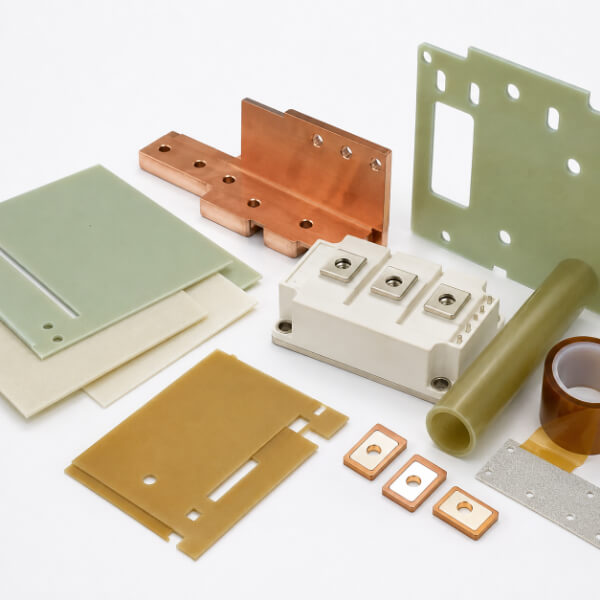
The materials that fill this second path form a working set. Each has a role, and each fails differently if misapplied. Here is the set as it appears in power electronics assemblies, and where it belongs.
The laminated busbar is the blood vessel of the power stage: stacked copper planes separated by thin insulation, carrying hundreds of amps while withstanding the full DC-link voltage. The insulation between planes must combine high dielectric strength with low dielectric loss, because the fast-switching voltage ripple between planes generates heat inside the laminate.
Two grades dominate. FR-4 (EPGC 202) offers high mechanical strength, excellent dielectric performance, and UL 94 V-0 flame retardancy — the default for stackup insulation and edge barriers. GPO-3 (UPGM 203) brings superior arc and tracking resistance, which matters where busbar surfaces can be contaminated or where creepage paths are short. For very compact busbar designs, the modified polyester resin of GPO-3 is often preferred precisely because of its tracking performance under polluted conditions.
Terminal boards, fuse boards, phase separators, and mounting angles hold the electrical geometry of the assembly. They are structural first, insulating second. This is where the G-10 to G-11 decision becomes a thermal-management decision in disguise.
G-10 (Class B, ~130°C) is adequate for conventional silicon IGBT assemblies where nothing around the board exceeds 120°C. G-11 (Class F, ~155°C and beyond) retains its mechanical strength at higher temperature because of a higher-temperature epoxy formulation. For SiC modules, where case temperatures routinely exceed 130°C, specifying G-11 for any load-bearing insulation next to the module is the difference between a board that stays flat for a decade and one that creeps, softens, and lets a phase barrier drift out of tolerance.
The gate driver sits at the same electrical potential as the emitter or source — but only a few millimeters of insulation away from the logic side that must stay isolated. Here the requirement is thin, tough, high-temperature insulation. The 6051 polyimide film handles continuous operation at 260°C with a dielectric strength above 200 kV/mm in thicknesses down to 0.025 mm — thin enough to fit tight driver-board stackups, tough enough to survive the thermal cycling of an inverter. Its resistance to solvents and oils also matters: gate-driver boards are the first casualty when conformal coatings or cleaning chemistries attack a lesser film.
DC-link chokes, EMI filters, and the module's own gate transformers all need interlayer and barrier insulation that survives elevated temperature without sagging. Aramid papers such as Nomex bring high temperature class with mechanical conformability, ideal for wrapping and layer insulation. Mica tape goes further: high-performance mica tapes combine phlogopite or calcined mica paper (≥65% mica content by weight) with fiberglass or PET backing, impregnated with fully cured epoxy or silicone resin. They withstand continuous operation above 130°C with short-term peaks above 800°C — which is why they appear wherever a winding or a cable must keep its dielectric identity through a fault.
There is one insulation job that is almost purely thermal: the fire barrier. In a fault — a failed semiconductor, a welded busbar joint, an arc — the local temperature can spike to hundreds of degrees in milliseconds. Organic insulation burns, drips, and conducts tracking. Mica, being mineral, does not burn and releases no toxic smoke. Mica tape, with its inorganic filler and fully cured resin, is specified as inner fire-resistant layers in power cables and as thermal shielding in modules where a single fault must not cascade into an enclosure fire. After immersion in transformer oil it retains at least 80% of its dielectric strength — a property that makes it the trusted last line in transformer-adjacent power electronics.
The following table places both philosophies side by side. Note how the priorities are mirror images.
| Position | Typical Material | Primary Job | Key Parameter | Failure Mode |
| Chip substrate (heat path) | Si₃N₄ / AlN ceramic (DBC, AMB) | Conduct heat, block voltage | Thermal conductivity 90-200 W/m·K | Crack, delaminate |
| Die attach / interconnect (heat path) | Sintered silver, copper ribbon | Carry current, conduct heat | Melting point, fatigue life | Fatigue, lift-off |
| Module-to-heatsink (heat path) | TIM: grease, pad, phase change | Fill air gaps, transfer heat | Thermal resistance Rth | Pump-out, dry-out |
| Busbar stackup (dielectric path) | FR-4 / GPO-3 laminate | Block DC-link voltage, carry load | Dielectric strength, tan δ, tracking | Self-heating, tracking |
| Terminal & mounting boards (dielectric path) | G-10 / G-11 epoxy glass | Hold geometry, insulate under heat | Thermal class B vs F | Creep, softening |
| Gate-driver isolation (dielectric path) | Polyimide film (6051) | Thin, high-temp isolation | 260°C, ≥200 kV/mm | Solvent attack, puncture |
| Magnetic components (dielectric path) | Nomex, mica tape | Layer & turn insulation | Thermal class, conformability | Wrinkle, short turn |
| Fire barrier (dielectric path) | Mica tape, mica laminate | Contain fault heat, no smoke | 800°C+ peak, non-combustible | — (mineral, doesn't burn) |
Wide-bandgap semiconductors do not just run hotter and switch faster — they change which insulation properties matter, and how much margin you need. Four shifts deserve attention.
SiC can produce voltage edges of tens to over 100 kV/µs. Fast edges create high-frequency voltage distribution across busbar and winding insulation, concentrating stress at edges, voids, and interfaces. The result is partial discharge — tiny internal sparks that erode organic insulation over time. Materials for SiC systems need PD resistance and void-free construction, which is why VPI-compatible mica tape and dense, low-void laminates become more attractive as switching speed rises.
As switching frequency climbs into the hundreds of kHz, dielectric loss (proportional to frequency × tan δ × voltage⊃2;) stops being a footnote. A busbar insulator chosen for its mechanical properties but with a mediocre loss tangent can now contribute real temperature rise. Specifying low-loss grades and measuring tan δ at the actual switching frequency — not at 1 kHz from the datasheet — is a discipline that separates SiC-ready designs from retrofits.
SiC junction temperatures reach 175-225°C. The dielectric path around the module follows: mounting insulation next to the case must migrate from G-10 (Class B) to G-11 (Class F), and fire barriers to mica, which does not have a conventional class because it outlives them all. Polyimide film, at 260°C, comfortably covers gate-driver isolation that older polyester films (155°C) cannot.
Higher bus voltages (800V platforms, soon 1200V+) plus compact inverters mean shorter physical distances and tighter creepage margins. This pushes designers toward materials with superior tracking resistance — GPO-3, melamine glass (G-9), and properly machined G-11 with clean edges — and toward careful edge finishing, because a rough, fiber-exposed edge is where tracking begins.
When a power electronics application reaches the specification stage, four questions are answered in order. The framework is simple, but it catches most mis-specifications:
What is the continuous temperature at the insulation surface? This sets the thermal class ceiling. Above 130°C continuous, G-10 is out; above 155°C, G-11 and mica take over. Around the SiC case, assume worst case plus 20°C margin.
What voltage and what switching speed does the insulation see? This determines dielectric strength, thickness, and whether partial discharge testing is required. Fast edges mean you must ask about voids and PD behavior, not just the kV/mm number.
Is the part structural or merely a barrier? Load-bearing insulation (terminal boards, phase separators, mounting angles) needs mechanical strength retained at temperature — that is the G-11 argument. Non-load-bearing barriers can use lighter, cheaper grades.
What happens in a fault? Fire-rated compartments demand mica. Surge-prone systems demand tracking resistance (GPO-3, G-9). Oil-immersed systems demand materials that hold dielectric strength after oil exposure — mica tape's 80% retention after oil immersion is why it keeps appearing in these specs.
For laminated materials, the thermal story does not end at the resin. It ends at the machining bench. Three details separate a part that survives its thermal environment from one that fails early:
Edge finish. A machined edge that is rough, frayed, or fiber-exposed becomes a tracking path and a moisture wick. Clean, well-sealed edges — cut with sharp carbide tooling, deburred, sometimes sealed — preserve the dielectric integrity that the sheet promised.
No delamination. Thermoset laminates must be cut with the right speeds and feeds. A delaminated layer near a bolt hole is a void, and a void under voltage is a partial-discharge site. A disciplined CNC operation treats every power-electronics part as a dielectric component first, a mechanical part second.
Tolerance under temperature. Laminates are dimensionally stable compared to thermoplastics, but a thin barrier in a hot, vibrating inverter can still fatigue at mounting points. Properly sized bolt insulation and insulating sleeves prevent the classic failure where a live busbar chafes through a barrier after years of micro-motion.
The trajectory is clear. Bus voltages move from 400V to 800V and beyond. Switching frequencies climb. Power density means less air, less space, less margin. Three material trends will follow:
More mica, not less. As fire safety standards tighten and thermal runaway scenarios are studied more carefully, mineral insulation migrates from niche to mainstream in EV and stationary storage compartments.
Low-loss laminate grades for high-frequency busbars. The busbar is becoming an electrical and thermal design element of its own, and loss data at switching frequency will become a standard datasheet request.
Hybrid stacks. Polyimide film bonded to mica, aramid papers combined with glass-reinforced resin — designers will stack material families to get thinness, temperature, and mechanical strength in one build, exactly as they already stack copper and ceramic inside the module.
The ceramic substrate manages the chip-level heat path — die to baseplate to heatsink. But the module also sits inside a system with busbars, terminals, gate-driver boards, magnetic components, and enclosure barriers. Every one of those carries voltage and generates or receives heat. System-level insulation materials — laminates, mica, and films — are what keep that surrounding structure safe and cool.
Common choices include FR-4 or GPO-3 laminates for busbar insulation, G-10 and G-11 sheets for terminal boards and mounting supports, polyimide film for gate-driver and control-board isolation, Nomex aramid paper and mica tape for magnetic components, and mica tape as high-temperature fire barriers near the module.
SiC switches faster and runs hotter. Higher dv/dt (up to 100 kV/µs) stresses busbar insulation with high-frequency voltage waves, demanding low dielectric loss so the insulator does not heat itself. Higher junction temperatures (175-225°C) push mounting and terminal insulation toward higher thermal classes such as G-11 (Class F) instead of G-10 (Class B).
The heat path is the chip-level chain — die, solder, ceramic substrate, thermal interface material, heatsink — engineered to conduct heat. The dielectric path is the surrounding insulation system — busbar insulation, terminal boards, barriers — engineered to block voltage while surviving the heat that the system produces. Both paths matter, but they are designed with opposite priorities.
Thermal management in IGBT and SiC modules is usually told as a chip-level story: ceramics, sintered silver, TIMs. But the module's survival also depends on a second, quieter story — the laminated busbar insulation that must not cook itself, the G-11 terminal board that must hold its geometry at 160°C, the polyimide sliver that isolates the gate driver, the mica barrier that must not burn when everything else does.
These materials are not passive witnesses to the thermal design. They are part of it. Specified with the same discipline as the substrate and the TIM, they keep the system inside its thermal envelope for its full design life. Specified by copy-paste from a previous design, they become the weak link in the one place you cannot afford one.


