
Views: 0 Author: Fenhar Publish Time: 2026-09-04 Origin: Site


Open a medium-voltage vacuum circuit breaker and trace the force path from the operating mechanism to the moving contact. Between them sits a composite member that most drawings label "insulating rod." Pick the part up, and the first thing you notice is that it is not solid. It is a tube — a hollow, filament-wound epoxy-glass cylinder, often a few hundred millimetres long, a few tens of millimetres across, with a wall only a few millimetres thick. That hollowness is not an economy. It is the design.
The member does something no other insulation component does: it carries full system voltage along its length and transmits the opening impulse of the mechanism at the same time. When the trip coil fires, the tube shoves the contact open in milliseconds against spring force, and the instant the contacts part, the tube is sitting across the live gap. This article walks through the material and design decisions behind that hollow component — and why treating it as a solid rod, or as a tube with a rod's thought process, produces the wrong part.
The distinction matters because the hollow section changes every subsequent decision. A solid rod is an axial member: strength in tension, stiffness in bending, and not much else to think about. A tube adds three things a rod never asks about:
A wall that must be sized for radial voltage. The insulating distance is no longer just the length; it is also the wall thickness, because voltage can sit across the wall as well as along the length. Wall thickness and winding density are now dielectric design variables.
A circumferential (hoop) direction. A rod has axial and transverse properties. A tube has axial, transverse, and hoop properties — and the hoop direction takes real loads: the spring stack pressing outward inside the bore, the metal end fitting clamped over the outside, radial forces at every support.
An interior surface that is also live. The bore is a second electrical interface. A sealed hollow member can breathe, condense moisture, and track on the inside — the inner surface is a creepage path few drawings ever dimension.
In short: a rod is a one-axis problem with a surface. A tube is a two-surface, three-axis problem — and the axis nobody checks is usually the one that fails.
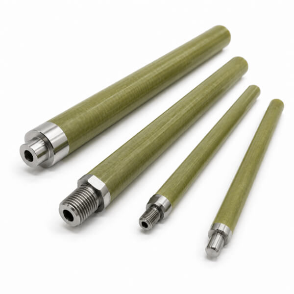
The roles a tube plays in a switchgear assembly impose very different loads, and the electrical orientation flips between them:
| Application | Mechanical Duty | Electrical Orientation |
| Breaker insulating pull tube (vacuum circuit breaker) | Transmits mechanism force to the moving contact; tension/compression with impact; bore houses the contact-pressure spring stack | Voltage along the length — outside creepage governs; recovery voltage after interruption |
| Operating tube (load-break switch, contactor) | Linear or rotational drive through an interrupter; repeated cycling; often clamped at both ends | Line and load voltage along length; switching transients |
| Bushing and lead-insulation tubes | Light structural duty; supports the conductor or winding lead | Voltage across the wall — through-wall dielectric and wall thickness govern; inner bore around the conductor is a live surface |
| Support and spacer tubes (bus, GIS, transformer coil formers) | Cantilever, compression, and clamping loads | Standoff insulation; creepage outside, sometimes across the wall at barriers |
| Tube insulators with molded or bonded sheds | Compression and cantilever; outdoor duty | Creepage along the shedded outside; bore must be sealed against ingress |
Read the last column and the theme is obvious: a tube is never "an insulator" in the abstract — voltage crosses it one way or the other, and which way decides the entire geometry. Along-length duty is a creepage problem (length sets the answer). Across-wall duty is a dielectric problem (wall thickness sets the answer). Most failures happen when the designer assumed one and the assembly delivers the other.
Before selecting a grade, map the failure paths — each one is governed by a different part of the tube.
For a slender tube carrying voltage end-to-end, the outside surface is the weak link. The wall's perpendicular dielectric strength — 14.5 kV/mm and up for a G11 wound tube — is generous, but the contaminated, humid air path along the outside is not. Rod length (plus sheds where the cubicle is tight) is set from creepage distance per kilovolt, derived from pollution class. This is the failure path every insulator engineer already knows — and it is the one that dominates pull-tube design.
Here is what separates tube design from rod design. A hollow member traps air. As the breaker breathes through temperature cycles, that air carries moisture in and out; if the bore is sealed at both ends, moisture can condense on the inner wall of a cold, dead breaker. The result is a conductive film on the inside of the insulation, tracking along a surface no inspection ever photographs. The bore is therefore a designed surface: it is either positively sealed with desiccant or dry-gas philosophy, vented so it cannot hold a pressure differential, or — in high-duty designs — made the deliberate home of the spring stack, with the internal creepage distance between the spring (earth side) and the far end calculated like any other gap.
Across the wall, failure starts long before dielectric breakdown — at partial discharges inside micro-voids left by imperfect wet-out. A tube wall is thin, so the electric stress per millimetre is high; a few voids at the fiber/resin interface become PD sites that erode inward over years. This is why wound-tube suppliers quote partial-discharge levels (single-digit pC for electrical grades), why void-free wet-out and controlled cure matter more than the headline kV/mm figure, and why machined tube ends must be sealed — exposed fiber ends at the cut are a wicking path straight into the laminate.
Mechanically, tubes fail in four characteristic ways. Impact — the opening shock is a dynamic load that can far exceed static mechanism force. Fatigue and fretting — every open/close cycle strains the bonded interface at the end fittings; after tens of thousands of cycles, the joint, not the tube, is what must be proven. Buckling — a long slender tube in compression is an Euler column, but a better one than a rod of equal weight, because the hollow section raises the radius of gyration. Crush and burst — the failure mode rods never face: a clamped fitting overtightened around a thin wall, a spring stack pressing outward, or internal pressure can split a tube longitudinally, exactly along the direction its axial fibers offer no resistance.
Here is the difference between a tube and a sheet or solid section: a tube's properties are programmed by the angle of its fibers, and that angle is set by the manufacturing process — not by the NEMA or IEC letter on the drawing. Two tubes with identical grade names but different winding architectures are different materials for design purposes.
| Tube Forming Method | Fiber Architecture | Strength Profile | Where It Fits |
| Filament winding (wet or prepreg) | Continuous rovings laid at controlled helix angles; hoop layers, helical layers, and low-angle layers can be stacked | Axial and hoop strength independently programmable by winding angle; seamless, void-controlled; the electrical-grade standard | Breaker pull tubes, GIS spacers, bushing cores, fuse tubes — anything with radial load, spring stacks, or across-wall voltage |
| Pultrusion | Continuous fibers running the full length only; no hoop reinforcement | Very high axial strength; minimal circumferential strength — splits longitudinally under radial or burst load | Axial-only duties where the tube is never clamped hard and never sees internal pressure |
| Rolled sheet (convolute) | Fabric wrapped in concentric layers | Balanced axial/hoop in principle, but layer-to-layer interfaces and seams are weak points for PD and moisture | Machined standoffs and general stock; rarely the first choice for high-voltage pull duty |
| Molded compound end parts + wound tube | Hybrid: wound tube body with molded bosses, flanges, or sheds bonded or over-molded on | Combines wound-tube strength with net-shape features (threads, sheds, mounting faces) | Where the tube needs integrated end geometry rather than a separate metal fitting |
Two rules follow. First, winding angle is a design dial: near-90° hoop layers carry radial load and resist burst; 45–55° helical layers balance axial and hoop; low-angle (15–30°) layers add axial stiffness for cantilevered members. A pull tube for a breaker wants mostly low-angle and helical fiber (axial drive) with enough hoop content to survive the clamped fittings and the spring stack; a bushing tube wants balanced hoop/axial architecture and a dense wall for across-wall voltage. Second, never substitute a pultruded tube where a wound tube is called for — a purely axial tube under internal pressure or hoop squeeze splits along its length, and that failure is instantaneous and total.
With the failure paths and the architecture in mind, the grade decision becomes legible:
| Grade | Resin System | Continuous Temperature | Why Choose It for a Tube | Watch-Out |
| G10 tube (EP GC 201, IEC 61212) | Epoxy | ~120–155°C (Class B–F) | General-purpose baseline; low moisture uptake, good balance, cost-effective for enclosed duty | Not for hot compartments or where a flame rating is specified |
| G11 tube (EP GC 203, MIL-I-24768) | High-temperature epoxy, halogen-free | 155–180°C (Class F–H) | Retains ≥50% of room-temperature flexural strength at elevated temperature; the default for vacuum-interrupter pull tubes and hot compartments; halogen-free matters in enclosed switchgear | Not inherently flame-rated (UL 94 HB class) — pair with enclosure fire barriers or step to FR5 where codes demand V-0 |
| FR4 / FR5 tube | Brominated / high-temp halogen-free epoxy | ~130°C / up to 180°C | UL 94 V-0 flame retardancy for open-air and dry-type switchgear, outdoor compartments, and code-driven cubicles | FR5 required when you need high temperature and flame rating together |
| G7 tube (silicone glass) | Silicone | 200°C+ | Outstanding arc resistance for hot, arc-prone compartments | Cost; lower mechanical strength than epoxy grades |
| Glass-phenolic / cotton or linen phenolic tube | Phenolic / melamine | ~120–170°C class | Economy, historical switchgear duty, arc resistance in some grades | Higher moisture absorption and more brittle than epoxy-glass; avoid in humid service |
Two grade decisions dominate real switchgear tube specifications. First, temperature class versus flame rating: G11 and FR5 are not the same material, and a drawing that asks for "G11, V-0" has asked for a combination no single grade delivers — it needs FR5, or a V-0 enclosure with a halogen-free G11 tube inside. Second, halogen content in enclosed gear: when the tube lives in a sealed cubicle, halogen-free G11 avoids corrosive byproducts in a fire, which is why it, not FR4, is the default for vacuum-interrupter pull tubes.
Where voltage crosses the wall, wall thickness follows the perpendicular dielectric requirement — typically 14.5 to 20 kV/mm and up for electrical-grade wound epoxy — derated for temperature, altitude, and service life, then checked against partial-discharge performance rather than just breakdown. Where voltage runs along the length, the wall still needs a mechanical minimum: enough section to carry the axial load, resist the clamped fitting's radial squeeze without crushing, and keep the tube round so the bore's internal clearance never closes.
The bore is where tube-specific failures hide. Three philosophies exist. Seal it — end caps or bonded fittings make the interior a closed volume, with desiccant where moisture is a risk; a sealed bore cannot exchange air, so it cannot pump moisture in on thermal cycles. Vent it — if the tube cannot be fully sealed, let it breathe deliberately through a filtered or labyrinth path so no pressure differential drives water inward past the end seals. Make the bore part of the design — where the spring stack lives inside, treat the internal gap from spring to far end as a calculated creepage distance and verify it like the outside. What is never acceptable is an unsealed, unvented bore that traps air and condenses: that is an internal creepage path waiting for its first cold night.
The most failure-prone region of any insulating tube is the interface where composite meets metal — and the hollow section changes the joint design compared with a solid rod:
External sleeve + internal spigot. The industrial standard for breaker pull tubes. A metal sleeve is bonded over the tube's outer diameter while a spigot or pin extends into the bore, so the fitting grips the wall from both sides. The bore is an asset here — the internal spigot centers the fitting, carries radial alignment, and gives the adhesive a second bonded surface. Load transfers over a long bonded area, fibers stay continuous, and any thread lives entirely on the metal part.
Pinned or clevis joints with crush protection. A transverse pin through the tube works only if the wall is thick enough to carry the bearing stress — and a thin wall will ovalize or crush under a bare pin. Standard mitigation is a local reinforcement: a metal insert in the bore at the pin location, or an external boss, so the pin bears on metal, not on unsupported laminate.
Direct threads into the wall. To be avoided in wound or pultruded tubes. Cutting a thread severs the fibers that carry the load at the exact point where the load enters, and in a thin wall there is simply not enough material for thread depth. Reserve threads for molded-compound bosses or generously over-thickened sections in low-duty applications.
Three interface rules apply to whichever joint is chosen. Length of engagement beats strength of adhesive: a long bond line distributes both the service load and thermal-cycling strain. Moisture must not reach the bond line or the cut ends: end faces are sealed at assembly — water wicking along the fiber/adhesive boundary or into exposed fiber ends is a slow, invisible killer. And CTE mismatch is real: the metal fitting and the composite expand differently over the operating range, so the joint must tolerate differential strain without debonding — flexible adhesive systems, not rigid ones, dominate this application.
In a vacuum breaker the contact-pressure spring stack often lives inside the pull tube. That makes the bore a mechanical interface too: the spring must bear on a shoulder or seat that does not crush the wall, the internal creepage gap must be maintained, and the spring end must not fret the bore surface over 10,000 operations. Designers who ignore the interior because "it's just a hole" end up with fretting debris and tracking in the very part they sealed to protect.
Orientation first. Determine where voltage crosses the tube — along the length, across the wall, or both at different sections — before any number is chosen. Along-length: creepage drives length. Across-wall: wall thickness and PD performance drive the section.
Creepage drives length; the bore is a second creepage surface. Set outside length from creepage per kV for the pollution class; add sheds where the cubicle is compact; and treat the bore's internal path with the same discipline.
Surface finish is a dielectric property. A machined tube surface that is rough or fiber-exposed collects contamination and tracks early. Smooth, well-sealed surfaces — with hydrophobic coating or silicone sheds where needed — extend the wet creepage path dramatically.
Moisture attacks from both surfaces. Epoxy-glass absorbs little (electrical-grade wound tubes typically ≤0.1–0.5% after 24 h immersion), but absorbed moisture lowers surface resistivity and reaches internal interfaces through unsealed ends and cuts. Seal end faces, bond lines, and every machined surface.
Test the finished tube, not the material. Tubes in breaker service are verified by routine tests on the assembly — power-frequency and lightning-impulse withstand, partial-discharge measurement, and mechanical endurance (typically 10,000 operations for class M2 mechanisms). The grade is one input; the winding architecture, the joints, and the sealed bore dominate the result.
Consider a vacuum circuit breaker pull tube for a 24 kV panel, rated for frequent operation. Working backward from the failure paths: voltage runs along the length, so the tube's insulating length is set by creepage across the polluted indoor gap, with sheds if the cubicle is tight; the member must push and pull the moving contact for 10,000 cycles, so the end fittings are bonded sleeve-and-spigot joints with sealed interfaces, and the bore is sealed to keep condensation off its inner surface; the contact-pressure spring stack lives inside, so the wall needs hoop fiber to carry the radial squeeze and the internal creepage gap is dimensioned like an outdoor clearance; the compartment runs warm, so the grade is G11 (Class F–H, halogen-free), not G10 — its retained strength at temperature protects the bond lines over the mechanism's life; and because the panel is enclosed and fire-conscious, the enclosure provides the V-0 barrier while the tube itself stays halogen-free. Every choice traces back to a failure path or a surface — and none of them would have been made by comparing dielectric-strength columns.
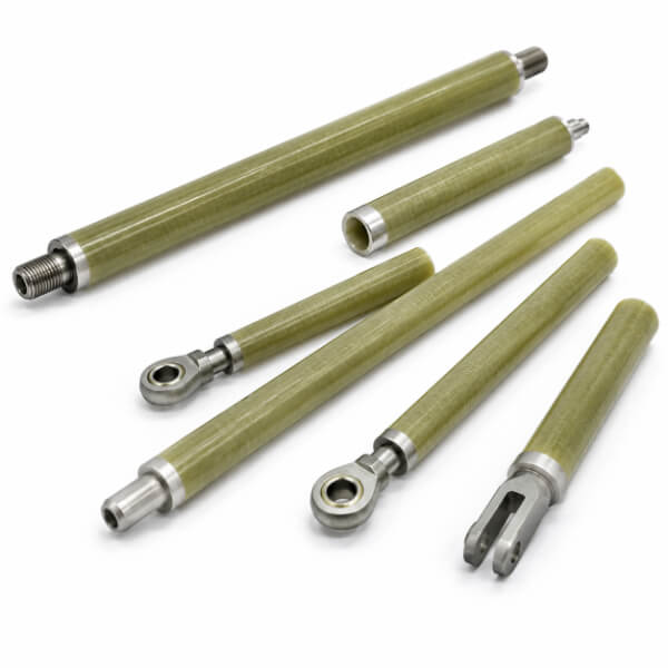
A hollow tube outperforms a solid rod on the three things a breaker pull member actually needs. First, stiffness per unit mass: moving the material away from the neutral axis into a thin wall gives far higher bending and column stiffness for the same weight, which matters for a part accelerated and decelerated on every open-close cycle. Second, the bore is functional space — in vacuum circuit breakers the bore houses the contact-pressure spring stack that holds the moving contact closed. Third, the hollow section sheds moving mass, so the mechanism can open the contacts faster. The tube is not a rod with a hole drilled through it; the wall, the diameter, and the bore are three separately designed surfaces.
Epoxy-glass filament-wound tubes dominate: G10-class tubes for general enclosed duty to about 130–155°C, and G11-class high-temperature tubes (Class F–H, 155–180°C) for compartments that run hot and for vacuum-interrupter pull tubes — G11 retains at least 50% of room-temperature flexural strength at elevated temperature and is halogen-free. FR4/FR5 flame-retardant tubes add UL 94 V-0 for open-air and dry-type switchgear. Silicone-glass G7 tubes serve hot, arc-prone compartments. Grades follow IEC 61212 / IEC 60893 (EP GC 201 / EP GC 203) and NEMA LI-1 tube equivalents. Choice is driven by operating temperature, flame-rating requirements, and whether the tube sits in an enclosed, gas-filled, or polluted environment.
Because the two processes build different fiber architectures. Pultrusion lays continuous fibers along the length only, so a pultruded tube is superb in axial tension but has almost no circumferential reinforcement — under radial or burst loading it splits along its length like a peeled log. Filament winding lays fibers at controlled helix angles, so hoop and axial strength can be programmed independently by winding angle. For any switchgear tube that carries radial load, clamps onto its outside, contains a spring stack, or could see internal pressure, a purely pultruded tube is structurally the wrong shape; wound architecture with hoop fiber content is required.
It depends on how the voltage is oriented to the tube, which is the mistake most grade-selection content makes — it assumes one answer. When voltage runs along the tube length, as on a breaker pull tube between the mechanism (earth) and the moving contact (line potential), outside surface creepage dominates and length is set by creepage per kV. When voltage runs across the wall, as on a bushing tube or a tube passing through a barrier, through-wall (perpendicular) dielectric strength and wall thickness govern. A well-designed switchgear tube identifies which orientation applies at every section — and remembers the bore: a sealed hollow interior can condense moisture and track on the inside, so the inner surface is a creepage path too.
The insulating member in a switchgear mechanism is easy to underestimate because it looks like a piece of hardware — and easier still to mis-specify, because it is drawn as a rod, described as a rod, and thought about as a rod. It is not. It is a hollow tube, and the hollowness is the design: a wall sized for the voltage that crosses it, a bore that is either sealed or deliberately used, hoop fiber where anything squeezes or pushes from inside, and end fittings engineered around a thin wall instead of into a solid one.


