
Views: 0 Author: Fenhar Publish Time: 2026-10-27 Origin: Site


A pouch-cell compression stack on glass epoxy plates: the laminate carries the load and stays electrically dead, while the cabinet behind it does the measuring.
Battery test equipment is specified on voltage, current and channel count. The laminate inside it almost never appears on the datasheet — yet it decides whether a 300 A pouch holder creeps at 60 °C, whether a probe plate holds registration across 256 channels, and whether a pack barrier survives a 960 °C glow-wire check. This is a part-by-part map of where the material sits, which models use it, and the parameters and standards to write on the purchase order.
Get this backwards and you ship a part that fails incoming inspection.
Both grades are woven E-glass cloth in an epoxy resin system, pressed and cured. The difference is a brominated flame retardant — usually tetrabromobisphenol A — carried in the FR4 resin and absent from G10. That one additive moves the flammability classification from HB to UL 94 V-0: a vertical specimen that self-extinguishes within ten seconds, without flaming drips.
Everything else stays close. Flexural strength sits above 340 MPa in both. Dielectric strength runs near 500 V/mil under ASTM D149. Water absorption stays under 0.20 % over 24 hours. Choosing FR4 over G10 costs you almost nothing mechanically and buys a fire rating.
The asymmetry is what catches people out. Structural G10 is not a PCB substrate grade. It carries no controlled dielectric constant, no dissipation-factor spec, and no copper peel-strength qualification. So FR4 moves into G10's territory freely, while G10 moving into FR4 territory fails three ways at once.
Consequence for test equipment: the moment a cycler cabinet goes for a CE mark or a UL listing, an insulation plate drawn as G10 becomes a finding. Draw it as FR4 from the start.
These are the numbers a receiving inspector or a design reviewer will ask for. Note the test method next to every one — a value without a method is not a specification.
| Property | Method | G10 | FR4 | G11 | EP GC 308 | GPO-3 |
| Specific gravity | ASTM D792 | 1.80–2.08 | 1.85–2.08 | 1.80–2.00 | 1.85–2.00 | 1.81 |
| Flexural strength, 23 °C | ISO 178 / ASTM D790 | ≥340 MPa | ≥340 MPa | ≥340 MPa | ≥340 MPa | 152 MPa |
| Flexural strength at 130 °C | ASTM D790 | — | — | — | — | 90 MPa |
| Flexural retention at 150 °C | IEC 60893-3-2 | — | — | ≥50 % | ≥50 % | — |
| Compressive strength | ASTM D695 | — | — | — | — | 228 MPa |
| Charpy impact, parallel | ISO 179-1/2 | ≥33 kJ/m² | ≥33 kJ/m² | ≥33 kJ/m² | ≥33 kJ/m² | — |
| Izod impact, parallel | ISO 180 | ≥34 kJ/m² | ≥34 kJ/m² | ≥34 kJ/m² | ≥35 kJ/m² | — |
| Electric strength, ⊥ in oil at 90 °C (3.0 mm) | IEC 60243-1 | ≥10.2 kV/mm | ≥10.2 kV/mm | ≥10.2 kV/mm | ≥10.2 kV/mm | 450 V/mil (air) 584 V/mil (oil) |
| Breakdown voltage, ∥ in oil at 90 °C | IEC 60243-1 | ≥35 kV | ≥35 kV | ≥35 kV | ≥35 kV | 47 kV |
| Insulation resistance after immersion | IEC 60167 | ≥5×10⁴ MΩ | ≥5×10⁴ MΩ | ≥5×10⁴ MΩ | ≥5×10⁴ MΩ | — |
| Volume resistivity | ASTM D257 | >10¹⁴ Ω·cm | >10¹⁴ Ω·cm | >10¹⁴ Ω·cm | >10¹⁴ Ω·cm | — |
| Water absorption, 1.5 mm | ISO 62 / ASTM D570 | ≤19 mg | ≤19 mg | ≤19 mg | ≤19 mg | 0.4 % |
| Glass transition, Tg | IPC-TM-650 2.4.25c | 130–140 °C | 130–140 °C (170 °C+ high-Tg) | 155–170 °C | — | — |
| Temperature index / thermal class | IEC 60216-1 | 130 °C (B) | 130 °C (B) | 155 °C (F) | 180 °C (H) | 155 °C (F) |
| Comparative tracking index | UL 746A | 175–300 V | 175–300 V | 175–300 V | — | >600 V |
| Arc resistance | ASTM D495 | — | — | — | — | 180 s |
| Glow-wire, GWEPT | IEC 60695-2 | — | — | — | — | ≥960 °C |
| Flammability | UL 94 | HB | V-0 | HB | — | V-0 |
Two rows in that table drive most sourcing decisions. The CTI row explains why pack barriers leave the epoxy family. The 150 °C flexural-retention row explains why a platen that holds its thickness at room temperature can still relax in a warm chamber.
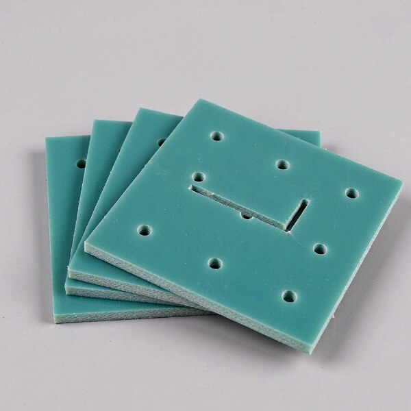
Sheet stock before machining. The woven glass cloth shows at the cut edge; the pale green cast is the epoxy resin system, not a coating.
A cycler is a metrology instrument wrapped in a fixture.
Walk the signal path and the laminate turns up at four points. Each asks something different of the material.
This receives the cell. The job is dimensional: put a 21700 can or a 100 mAh pouch in the same place, cycle after cycle, without conducting.
One cycler maker publishes this layer as a standard accessory line with part numbers, which makes it the clearest window into what the industry actually buys:
| Part | Type | Max current | Cell envelope |
| PN 121830 | 16 mm coin cell holder | 5 A | OD <16 mm, H 1.2–3.2 mm |
| PN 405788 | 20 mm coin cell holder | 5 A | OD <20 mm, H 1.6–3.2 mm |
| PN 121822 | 23 mm coin cell holder | 5 A | OD <23 mm, H 1.6–3.2 mm |
| PN 121814 | 30 mm coin cell holder | 5 A | OD <30 mm, H 1.6–3.2 mm |
| PN 409714 | Universal coin cell holder | 3 A | OD 10–30 mm, H ≤7 mm |
| PN 409716 | Universal 8-cell coin tray | 3 A | OD 10–30 mm, H ≤7 mm |
| PN 409722 | 10 A cylindrical holder | 10 A | OD 10–40 mm, L 20–120 mm |
| PN 409724 | 30 A cylindrical holder | 30 A | OD 10–40 mm, L 20–120 mm |
| PN 409726 | 60 A cylindrical holder | 60 A | OD 10–35 mm, L 20–120 mm |
| PN 432636 | 200 A cylindrical holder | 200 A | OD 10–50 mm, L 10–120 mm |
| PN 470546 | 200 A cylindrical holder | 200 A | OD 10–60 mm, L 10–200 mm |
| PN 414162 / 414164 / 414166 | 8-cell cylindrical trays | 10 / 30 / 60 A | OD 18–21 mm, L 40–85 mm |
| — | 10 A flat / pouch holder | 10 A | Pouch |
| — | 60 A flat / pouch holder | 60 A | Pouch |
| — | 300 A flat / pouch holder | 300 A | Pouch, L <200 mm, W <285 mm |
| — | 300 A prismatic holder | 300 A | Prismatic |
| — | 300 A prismatic holder, H = 300 mm | 300 A | Prismatic, tall format |
| — | Universal tray | — | Mixed formats |
Two details matter more than the ratings. The holders are described as mounted on a circuit board and plugging straight into the cabinet interface — that board is a laminate part, not a metal bracket. And an eight-position tray carries several times the machining content of a single holder, which tells you where the value sits.
Other holder families in circulation cover the same ground differently: an adjustable cylindrical holder that spans button cells through 21700 in one eight-position body; true four-wire Kelvin holders in AAA / AA / C / D / 18650 / 21700 and 9 V; and coin holders combining a thumbscrew terminal at one end with a spring contact at the other. Coin, cylindrical and pouch jigs also appear as plug-in options on Korean and Japanese cycler platforms.
Pouch cells are cycled under pressure. Not clamped loosely — pressed, at a controlled force, for weeks. The laminate platen transmits that force evenly across the cell face while staying electrically dead.
This is the most heavily cited application in the literature. Work on lithium-metal / NMC811 pouch cells compared constant-gap against constant-pressure fixture designs at initial pressures of 2, 10 and 30 psi, with the constant-gap arm interfacing the cell against either a Garolite G10 rigid plate or a 1/16-inch porous silicone foam layer; the constant-pressure spring ran at about 6.5 lbf/in. The stated reason for picking G10 is unglamorous and correct — it is stiff, flat, insulating, and it does not relax under a sustained load in the hundreds of kilopascals.
Independent work on NMC/graphite single-layer pouch cells put the useful window higher: 0.66 to 1.98 MPa, with roughly 1.3 MPa the best point for limiting cyclable-lithium loss. Related work on larger formats found 75 kPa to 2200 kPa, optimum around 1200 kPa.
Convert those into hardware and you get the failure mode the grade choice prevents. A 1.3 MPa load over a 100 mm × 100 mm pouch face is roughly 13 kN. On a platen sitting in a 60 °C chamber for a month, any resin softening shows up as thickness drift and a slow loss of stack pressure — which then shows up in your data as a capacity-fade artefact.
| Duty | Temperature at the part | Grade | Reason |
| Room-temperature cycling, light load | 20–40 °C | G10 or standard FR4 | Stiff, economical, machines clean |
| Hot-press formation (typical production window) | RT to 90 °C, under 200–5,000 kgf | G11 / EP GC 203 | 155 °C thermal class; ≥50 % flexural retention at 150 °C |
| High-temperature formation | to 180 °C | EP GC 308 | 180 °C temperature index, Class H |
| Any of the above in a certified cabinet | — | FR4 or FR5 for insulating layers | UL 94 V-0; G10 will not clear the flammability review |
Related part names in this zone: compression plate, pressure plate, backing plate, support plate, spacer and shim, load-cell mount plate, spring platen, and the disc spring stack that sets the constant-pressure curve.
Where a formation line touches hundreds of cells at once, it touches them through spring probes. The architecture is the one electronics manufacturing has used for decades: a probe plate drilled at the exact coordinates of each test point, holding probes in receptacles and wiring back to the interface connector; a top plate carrying push fingers that presses the device down without bowing it; and guide pins picking up tooling holes for registration.
The laminate carries all three. Probe plates and guide plates are the classic machined glass epoxy parts in automated test — they hold hole position to within a few thousandths of an inch across a plate that may be half a metre long, they do not conduct, and they survive daily handling.
Machined suppliers commonly work to ±0.05 mm on positioning and cutouts, ±0.03 mm on hole position for probe guidance, minimum drilled hole around 0.8 mm, and slot widths from 1.5 mm. Those are the tolerances the plate is bought for.
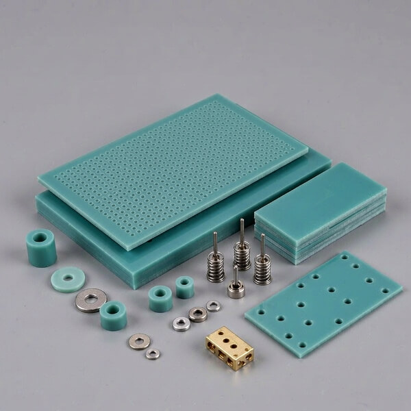
The machined part family: probe plates drilled at test-point coordinates, compression and backing plates, shims, bushings, spring probes and a gold-plated copper contact block.
The probes themselves are the consumable. A well-made spring probe holds consistent force past 500,000 cycles, and the failure is gradual — spring fatigue drops contact force below what is needed to break through surface oxide, and you start chasing intermittent readings that look like cell defects. Production lines replace them on a schedule.
Specify probes on four parameters. Centre spacing first: 100 mil (2.54 mm) is the common pitch, with 75 and 50 mil available at lower force and shorter life. Then tip geometry, the spring force delivered at working travel, and the current the barrel must carry.
Crown — four or more contact points in a ring. The default, with redundancy when one point lands on contamination.
Serrated — teeth that cut through flux residue and oxide. Use it on uncleaned surfaces; it will chew soft gold pads.
Flat — large smooth area. Gentlest option for gold-finished or delicate surfaces.
Spear — concentrated force for vias and plated holes.
Cup — self-centres on component leads and pins.
Chisel — contacts a line rather than a point, for lead rows.
A typical 100 mil probe works at 4–8 oz of force with 1.5–2.5 mm of working travel. Add up the array before you size the actuator: 300 probes at 6 oz is about 112 lbf, or roughly 500 N, and the push fingers have to resist all of it.
Above roughly 60 V the job changes from hold-and-locate to stop-the-arc. This is where epoxy glass stops being the automatic answer.
GPO-3 is the grade that gets specified, and it is not an epoxy. The matrix is unsaturated polyester, the reinforcement is glass mat rather than woven cloth, and it is covered by IEC 60893-3-5 UP GM 203 instead of 60893-3-2. It also answers to DIN 7735 HM 2471 and NEMA LI 1 GPO-3, and turns up in trade as UPGM203 board or red barrier board.
| Property | Method | Value |
| Comparative tracking index | UL 746A | >600 V |
| Arc resistance | ASTM D495 | 180 s |
| Glow-wire flammability, GWEPT | IEC 60695-2 | ≥960 °C |
| Inclined-plane track resistance, 1/4 in at 2.5 kV | ASTM D2303 | 1,000 |
| UL high-voltage track rate | UL 746A | 0 in/min |
| Dielectric strength, perpendicular, in air | ASTM D149 | 450 V/mil |
| Dielectric strength, perpendicular, in oil | ASTM D149 | 584 V/mil |
| Breakdown voltage, parallel, in oil | ASTM D149 | 47 kV |
| Tensile strength | ASTM D638 | 55 MPa (8,000 psi) |
| Flexural strength at 23 °C / at 130 °C | ASTM D790 | 152 MPa / 90 MPa |
| Compressive strength | ASTM D695 | 228 MPa |
| Shear strength | ASTM D732 | 80 MPa |
| Izod impact, notched | ASTM D256 | 8.9 ft-lb/in |
| Water absorption | ASTM D570 | 0.4 % |
| Dielectric constant / dissipation factor at 60 Hz | ASTM D150 | 4.1 / 0.013 |
| Insulation resistance | ASTM D257 | 3.1×10¹² Ω |
The comparison that decides it: FR4 tracks in the 175–300 V CTI band, while GPO-3 sits above 600 V and takes three minutes to arc through. On a pack-level barrier, that is the difference between a part that survives a fault and one that carbon-tracks.
Part names in this layer: phase barrier, interphase partition, end barrier, arc shield, arc-extinguishing chamber spacer, busbar support and insulator, mounting panel, insulating support, slot wedge, safety baffle, insulating washer, cable clamp, switchgear barrier. End-of-line pack test stations in the 8720 class list pressure insulation among the checks they perform, which is a fair signal of what pack builders care about.
Below is the equipment that matters for laminate volume, grouped by class rather than by badge. Formation lines consume the most material per machine; research cyclers consume the least per unit but specify the most per part.
| Model / class | Rating | Laminate parts |
| HPC facility-type hot-press formation system | 200–5,000 kgf, RT to 90 °C | Hot-press platens, cell nests, insulator sets |
| PPC box-type hot-press formation system | Two-layer stacked box design | Platens, box-level insulator sets |
| VPC vacuum pre-charger | Cylindrical and prismatic; per-cell vacuum control | Cell nests, vacuum-port insulation |
| 46-series formation charger/discharger | Fixture and power stage integrated; 1 frame / 4 boxes; 144 ch | Integrated fixture plates, insulators |
| HBRF0510 formation system | 32 ch/box × 36 boxes = 1,152 ch; −5 to 5 V at 0.1 mV; ±100 mA to 10 A at 1 mA | 1,152-position tray sets, nest plates |
| MCFT-BD formation system | 2 A / 5 A / 10 A versions; 4–32 and 4–64 circuits per module; 320 / 384 / 384 circuits per cabinet; >500 amplifiers per m² | Formation tray insulation, clamp bodies |
| 17000 formation system | 100 kW×14 / 200 kW / 200 kW×14 / 300 kW×14; 5–850 V and 100–1,700 V; 0.1 % FS | Formation trays, high-voltage insulation sets |
| SPT formation (series-parallel) | 336 ch for 18650/21700; 128 ch for 46xx | Trays, nest plates, platens |
| High-temperature pressing JIG formation system | Heated and pressed formation, adjustable pressure | Pressing JIG platens, spacers |
| Integrated formation and grading system | Pressed, constant-temperature charge/discharge | Platens, restraining trays |
| Grading system | Up to 72 ch; SMPS power stage | Contact plates, tray insulation |
| CT-4000 series (CT-4008 chassis) | CT-4008-5V60A-NTA: 300 W/ch, auxiliary channel −25 to 110 °C; ±0.05 % FS | Clamp bodies, trays |
| CT-8002S-5V100mA, CT-9002-5V6A | Portable, with cyclic voltammetry | Coin and polymer clamp bodies |
| 3C hot-press formation and grading fixture machine | 16 ppm | Hot-press platens, fixture plates |
| Bluetooth-cell hot-press formation and grading machine | 15 ppm | Platens, small-format nests |
| Negative-pressure loader | ≥20 ppm; loads and unloads restraining trays | Restraining trays, fixture plates |
| DCIR tester / OCV-ACIR tester | DCIR tester at high rate; OCV/ACIR at ≥20 ppm | Contact plates, insulating spacers |
| 固态 battery EOL combined tester | ≥12 ppm; insulation and leakage testing integrated | Insulation test fixtures |
| Model | Rating | Laminate parts |
| LBTS-Cell | 0–5 V / 0–10 V; 10 µA–500 A/ch; 4–256 ch | Holder bodies, platen insulation |
| LBTS-Cell High Throughput | 0–5 V; 1 mA–1 A or 10 A/ch; 192 or 256 ch | Tray plates, nest arrays |
| RBT-Cell | 0–6 V / 0–20 V; 100–400 A/ch, to 1,600 A paralleled; 4–64 ch | High-current holders, busbar supports |
| LBT-Benchtop | 0–5 V; 100 µA–10 A/ch (1 A / 5 A / 10 A models); 8–16 ch | Holder bodies, chamber trays |
| HPS ultra-high precision | ±6 V; 100 µA–5 A/ch; 6 auto ranges; 2 ch per unit | Precision holders |
| PDBT parallel differential | 1 mA–5 A; 4 ranges; 8 parallel differential channels | Matched holder set |
| LBTS-MZTC | 5 / 10 / 20 A/ch; 32 ch; 16 isolated thermal zones at 10–60 °C ±0.5 °C | Chamber trays, per-zone holders |
| SBTR smart battery tray | 30–200 A/cell; 4–96 ch; per-cell thermoelectric control | Tray structure, cell nests |
| Series 4000 | 1–96 ch; 1,400 A / 14,400 W; 1 or 4 ranges; 2 / 5 / 10 ms step | Three holder families, platen insulation |
| Series 4000H | 1–96 ch; 2,400 A / 28,800 W; 2 or 3 ranges | High-current holders, busbar supports |
| Series 6500 | 3,200 A / 16,000 W; 3 ranges; 10 ms step | High-current holders |
| Series 6600 high density | 1–192 ch; 1 A max; 4 ranges; 20 ms step | Matched holder arrays |
| MCT-RE | 100–200 A and above; up to 48 ch per cabinet | Holders, terminal boards |
| MCT-RE II | 300 A and above; up to 48 ch per cabinet; high accuracy | Holders, busbar supports |
| MCT-HD | 2–10 A and above; up to 384 ch per cabinet | High-density nest plates |
| MCT-ME | 50–150 A; linear amplifiers | Holders, insulators |
| BTDC4-100/10-6, BTDC4-300/30-6, BTDC2-300/30-6 | −6 to +6 V; 4 or 2 circuits per module; 100 / 300 / 600 A; pulses to 150 / 450 / 900 A for 30 s | High-current holders, platen insulation |
| BTDC4-100/10-20, BTDC2-300/30-20 | −20 to +20 V; 100 / 300 A | Module-level holders |
| MCV | 0–18 V; 1 µA–300 A, 2,700 A paralleled; up to 96 circuits; ±0.05 % FS | Cell holders, pressure-monitor fixture blocks |
| WBCS3000S / M1 / M2 / D / HP | 50 / 100 / 200 / 400 W per channel and above; ±0.02 % f.s. | Coin, cylindrical and pouch jigs |
| WBRS10-128, WBRS50_8 | Up to 128 ch per rack; 1 A or ±5 A | Rack trays, jigs |
| TOSCAT-3000 | 100 mA / 1 A; up to 100 ch per unit; pressure measurement optional | Pressure fixture blocks, holders |
| TOSCAT-3600 | 6 A; −1 to 4.5 V; 128 ch | Tray plates |
| TOSCAT-3200 | 10 / 60 / 120 / 240 / 500 A; pack to 500 V | Pack insulation, busbar supports |
| TOSCAT-5200 | 3–5 / 6–10 / 15 A; 500 µs pulse width | Pulse fixture holders |
| CTS cell test system | to 6 V / 5 A (20 A paralleled); 32 ch; 200 nA resolution | Battery holders (separate product line) |
| BCS-1012 | 32 ch in 8U | Matched holder set |
| BCS-975R | 8 × 75 A, to 2 × 300 A | High-current holders |
| CT3001A / CT3001C / CT3001K | 8 ch per module; 100 mA–5 A at 5 V; 0.05 % RD ± 0.05 % FS | Coin and cylindrical holders |
| CT3002A / AU / K / N | 8 ch; 10 mA to 20 A versions; sampling to 10 pts/s | Coin and cylindrical holders |
| Cell Fixture Shelf | Prismatic, pouch and cylindrical; 12 ch | Shelf structure and insulation |
| Model | Rating | Laminate parts |
| LBTS-Module | 20–100 V; to 80 A/ch; up to 32 per chassis | Busbar supports, barriers |
| RBT-Module | 30–200 V; 75 / 150 / 300 A/ch, to 1,800 A paralleled; 2–24 ch | High-current busbar supports |
| RBT-Pack | 300–1,500 V; 100 / 150 / 200 A/ch; up to 6 ch | Pack barriers, arc shields |
| 17020 | 600 W to 60 kW per channel; 20 / 60 / 100 / 200 / 500 V modules; 2,600 A paralleled; up to 60 channels paralleled | Module insulation, busbar supports |
| 17020C | 10–80 kW/ch; 150 V; 100 A/ch to 800 A paralleled; 1–8 ch; 18-bit; 0.02 % FS voltage; 5 ms to 90 % | Module barriers |
| 17020E | 10–80 kW/ch; 60 / 100 / 200 V; 100–800 A/ch | Module barriers |
| 17040 | 60 / 120 / 180 / 250 / 300 kW; 60–1,000 V; ±0.1 % FS; 50 kHz sampling; 2 ms current transition | Pack barriers, chamber fixtures |
| 17040E | to 1,700 V / 4,800 A / 1.2 MW | High-voltage barriers |
| 17050 | 1–4 ch; 6 kW–1.08 MW; 33 V–2,000 V at full power | Barriers, guarded fixtures |
| 17060 | AI server BBU and EV pack; ±0.02 % of range; 50 kHz | BBU insulation, pack barriers |
| UBT-RE | to 20 V; 150 A and above | Module barriers |
| UBT-HD | to 18 V; 10 / 20 / 40 A; grid regeneration | Module insulation |
| BNT-IGBT | to 150 V / 500 A; grid regeneration | High-current busbar supports |
| BNT-Me | 10–60 V; linear amplifiers | Insulating supports |
| IBT-IGBT | 60 A to 3,200 A, traction batteries | Heavy busbar supports |
| DCA Tester | Dynamic charge acceptance, lead-acid | Terminal boards |
| SL1000A (discontinued, supported) | ±360 kW; 50–1,000 V; ±200 / 300 / 600 A, ±2,400 A paralleled | Pack barriers, guarding |
| SL1700A series, SL1710A, SL1730A, SL1740A | to 300 kW pack level; 100 / 200 / 300 kW versions | Pack barriers, busbar supports |
| SL1002A | Cell level, 600 A | High-current holders |
| CE-6000 series | Cell, module and pack; to 3,000 V | High-voltage barriers |
| CE-6002-200V200A-EOL | Pack end-of-line; 200 V / 200 A | EOL insulation fixtures |
| ITS5300 | 0–2,250 V; 0–8,000 A; 3U modules at 18 kW; 95 % regeneration; 1 ms sampling | Pack insulation, busbar supports |
| 8720 pack ATS | 5–350 kW; 0–900 V; 0–1,000 A; EOL including pressure insulation | EOL insulation, barriers |
| 8610 / 8630 | Pack power HIL / BMS power HIL testbeds | Insulating supports, guards |
| 9200 series | High-power pack test | High-voltage barriers |
Ask a formation line builder for a fixture catalogue and you get trays, clamps and probes.
The one that carries the current and the pressure rarely appears. It gets bought as a machined assembly from a specialist instead.
| Parameter | Part 0800060405CP | Part 0800050405CP |
| Description | 5 V / 60 A pressure formation board | 5 V / 30 A pressure formation board |
| Configuration | Four-wire | Four-wire |
| Main material | FR4 + gold-plated copper | Gold-plated copper + epoxy resin |
| Rated current | 60 A | 30 A |
| Contact resistance | <10 mΩ | — |
| Temperature rise | <15 °C | — |
| Surface finish | Insulated | Gold plated |
| Flammability | UL 94 V-0 | UL 94 V-0 |
| Service life | 30,000 press cycles | 30,000 press cycles |
| Ambient range | −20 °C to 120 °C | −20 °C to 120 °C |
Read the material line again. The pressure formation board is a glass epoxy laminate part. It is pressed against a pouch cell at force, carries tens of amps through plated copper, must be V-0, and must survive thirty thousand cycles between −20 °C and 120 °C. That specification is the whole argument for treating the laminate as engineered rather than commodity.
A second production line in the same class is built on FR4 copper-clad laminate with 1 to 6 oz copper and an immersion gold finish, in a 110 × 68 × 1.6 mm body rated 0–20 A, fixture resistance ≤5 mΩ, ambient ≤100 °C, thickness machinable from 1.2 to 6.5 mm. Copper weight is the variable worth noticing — it sets how much current the board carries before temperature rise shortens its life.
Note on sourcing. These figures come from supplier product listings, not from a standard. The same part number appears across listings with slightly different current ratings and contact-resistance values, so confirm the current datasheet before designing around a number.
The surrounding part family on a formation line RFQ includes formation trays, formation clamps, aging fixtures, tunnel-oven probe boards, vacuum-oven contact boards, conductive contact plates, high-current PCBs and high-temperature pressure formation boards. On vacuum-oven parts the design detail that matters is an extended high-temperature polymer guide sleeve: it stops sliding friction from generating metal particles and prevents arcing under vacuum.
Pouch-cell pressure formation fixtures in this class commonly run at about 5.5 kg per station, with a medium-soft silicone contact face that spreads the load across an uneven cell surface and resists electrolyte corrosion.
| NEMA LI 1 | IEC 60893 | DIN 7735 | IPC-4101 | MIL-I-24768 | Thermal class | Temp. index | Flame |
| G-10 | EP GC 201 | Hgw 2372 | /20 | /2 (GEE) | B | 130 °C | HB |
| FR-4 | EP GC 202 | Hgw 2372.1 / F881 | /21 | /27 (GEE-F) | B | 130 °C | V-0 |
| G-11 | EP GC 203 | Hgw 2372.4 | /22 | /3 (GEB) | F | 155 °C | HB |
| FR-5 | EP GC 204 | Hgw 2372.2 | /23 | — | F | 155 °C | V-0 |
| — | EP GC 205 (roving fabric) | — | — | — | H | 180 °C | — |
| — | EP GC 306 (high CTI) | — | — | — | F | 155 °C | V-0 |
| — | EP GC 307 (high CTI) | — | — | — | F | 155 °C | — |
| — | EP GC 308 | — | — | — | H | 180 °C | — |
| GPO-3 | UP GM 203 (60893-3-5) | HM 2471 | — | /6 | F | 155 °C | V-0 |
For FR4, the IPC-4101 slash sheet is how you control glass transition. /21 is standard FR4, with a Tg floor around 110 °C on the sheet and typical commercial values of 130–140 °C. /24 requires ≥150 °C. /26 requires ≥170 °C. /129 is halogen-free at ≥150 °C, with bromine and chlorine each below 900 ppm under IEC 61249-2-21. Compare two datasheets only after checking the IPC-TM-650 method — Tg by DSC (2.4.25c) and by TMA (2.4.24c) are not the same number.
IEC 60893-3-2 is the one to cite for structural sheet, and its minimum acceptance values are what a receiving inspector checks:
Flexural strength, ISO 178: ≥340 MPa
Charpy impact parallel to laminations, ISO 179: ≥33 kJ/m²
Izod impact parallel, ISO 180: ≥34 kJ/m²
Electric strength perpendicular, 90 °C in oil, 3.0 mm, IEC 60243-1: ≥10.2 kV/mm
Breakdown voltage parallel, 90 °C in oil, IEC 60243-1: ≥35 kV
Insulation resistance after water immersion, IEC 60167: ≥5×10⁴ MΩ
Water absorption, 1.5 mm, ISO 62: ≤19 mg
Thermal endurance for EP GC 308, IEC 60216-1: TI ≥180
Flammability for EP GC 202 and 204, IEC 60695-11-10: V-0
One trap worth flagging. A Chinese GPO-3 datasheet quoting 130 MPa tensile is not overstating, and an American one quoting 8,000 psi is not underselling. They are different methods — IEC 60893-2 versus ASTM D638 — with different specimens and fixtures. Print the method next to the number or you will spend a week explaining a phantom quality gap.
On the equipment side, the standards driving fixture requirements are IEC 62660-1 for cell performance and reliability, GB 38031 for traction battery safety, UL 2580 for EV batteries, UN 38.3 for transport, and the drive profiles — NEDC, FUDS, HPPC, DST, ECE-15L — that formation and cycler platforms simulate directly. Pack testers are published against IEC, ISO, UL and GB/T.
Grade and standard together. "FR4 to IEC 60893-3-2 EP GC 202, UL 94 V-0" — not "FR4 sheet".
Tg with its method. "Tg ≥150 °C by IPC-TM-650 2.4.25c (DSC)".
Electrical values at the specimen condition. Electric strength at 90 °C in oil, not at room temperature in air.
Method next to every mechanical number. ASTM or IEC, stated explicitly.
Geometry on the drawing. Thickness and tolerance, hole diameters, edge distances, countersinks, and the edge break. Machined glass epoxy edges are normally deburred as standard; a 0.5–1.0 mm chamfer or an R0.5–1.0 mm radius is a separate call — and worth making, since a chamfer also eases assembly insertion and a radius reduces exposed glass fibre where parts are handled often.
Matched sets, if plates must agree. A probe plate and a guide plate only work as a pair. State on the print that they are a matched set, give the dowel scheme with fit classes, and give the stack height that sets standoff length.
Documents. UL 94 file, RoHS certificate to 2011/65/EU with 2015/863, REACH SVHC declaration, and lot traceability. RoHS and REACH are two separate documents and European auditors usually want both.
In most cases yes, and you pick up a fire rating on the way. The two share a resin system and a reinforcement. FR4 simply carries a brominated additive that G10 does without, so stiffness and breakdown behaviour stay close.
The reverse swap is where drawings fail. A G10 part brings no flame classification on file, no commitment on dielectric constant, and no peel-strength history to show an inspector.
Usually resin softening in the platen. At the top of a typical hot-press formation window, a 130 °C-index laminate under sustained load drifts in thickness, and the pressure you set at the start quietly falls away. The fix is a 155 °C-class platen.
Once the part stops being a holder and starts being a barrier. Cell-level fixturing gets away with epoxy glass. Pack voltage does not — you want a tracking index over 600 V rather than two or three hundred, three minutes of arc resistance, and a glow-wire figure above 960 °C.
Phase barriers, arc shields and busbar supports all fall on that side of the line.
Rated life on a decent probe runs past half a million compressions. Watch your pass rate rather than the calendar.
Contact force decays gradually as the spring fatigues. The first symptom is scatter in the readings — data that looks like a batch of bad cells but is really a contact that stopped cutting through oxide. Most plants therefore replace on a fixed schedule instead of waiting for failures.
When you specify, four parameters decide it: centre spacing, tip geometry, the force the spring delivers at working travel, and how much current the barrel has to carry.
It is not, though it sits beside them in every laminate catalogue. Polyester carries the load instead of epoxy, and the glass arrives as chopped mat rather than woven fabric.
The consequence shows up on the paperwork. IEC 60893-3-5 UP GM 203 governs it, not 60893-3-2. German and North American drawings instead call out HM 2471 to DIN 7735, or GPO-3 to NEMA LI 1.
Positioning and cutouts at ±0.05 mm is the common working figure, with hole position at ±0.03 mm where probe guidance is critical. Minimum drilled diameter around 0.8 mm, slot widths from 1.5 mm. Hold the whole stack height on the print, not per plate, if the plates must register together.


