
Views: 0 Author: Fenhar Publish Time: 2026-11-19 Origin: Site


Start by placing the part. A solid rod earns its place where the load runs along its axis, where it must stand off a conductor in compression or cantilever, or where the end needs a machined feature. It is not the default shape for every insulating member, and the breaker pull path is the classic case where it is the wrong one.
| Role in the assembly | Dominant load | Voltage orientation | Why a solid rod |
| Busbar support insulators and standoffs | Compression plus short cantilever from bus forces | Standoff creepage outside; dielectric across the section if it crosses a barrier | Full section resists compression; a thread or boss can be machined straight into the ends |
| Disconnector and load-break switch operating linkages | Axial push/pull with switching impact | Longitudinal — creepage sets the length between live and earthed ends | High axial stiffness at a small diameter; no bore required |
| Phase spacers and barrier ties | Compression and vibration | Between phases — dielectric across the rod section | Rigid, dimensionally stable spacing with simple through-fastening |
| Insulating tie rods, threaded shafts, adjustable feet | Tension or compression with a bolted interface | Low-voltage or earthed-zone duty in most designs | Threads cut into solid stock replace a separate clamped fitting |
| Contact-rod guides and VCB pole internals | Sliding guidance, light radial contact | Longitudinal within the pole | Precision-machined diameter and good surface finish; no internal spring space needed |
Read the last column and a pattern appears: the rod is chosen for what its solid section lets you do — carry compression, machine a thread, hold a diameter. Those are exactly the things a hollow tube gives up. This is the practical boundary between rod and tube, and it is a mechanical boundary first and an electrical one second.
The distinction is worth stating plainly because the two parts share resin systems, grade names, and catalogue pages. A slender rod is a one-axis member with a surface: it carries load along its length and insulates along that same length. It has no internal cavity to seal, no bore that can condense moisture, and no hoop direction that a clamped fitting loads from inside.
That sounds simpler than a tube, and in one sense it is — the third surface that haunts a tube simply does not exist in a rod. But the solid section concentrates its own risks elsewhere. The entire cross-section is the load path and the dielectric at once, so impact, machining damage, and fiber orientation all act on the same material. A nick on a rod's surface is not a cosmetic defect: in a brittle composite it is a stress raiser that grows into a through-crack, and a transverse crack in an insulating rod is an electrical event as much as a mechanical one. Specifiers who move from tubes to rods and simply "ignore the bore" tend to miss this.
Here is the decision that matters most and appears least often on a quote: the grade name on the quote says nothing about whether the fibers run straight or wrap. Two rods both labelled "epoxy glass G-10" can behave like different materials because the manufacturing process programs their fiber architecture. There are two mainstream routes, and a third, older one.
| Rod process | Fiber architecture | Strength profile | Where it fits |
| Pultruded (continuous pulling through a heated die) | Continuous rovings running axially; essentially no circumferential fiber | Highest axial tensile strength and stiffness per cost; weak radial compression; prone to lengthwise splitting under side load | Light axial duty, long continuous lengths, cost-driven linkages and spacers |
| Wrapped / laminated (resin-impregnated cloth wound and cured under heat and pressure) | Concentric layers with cross-directional reinforcement | Lower pure tensile strength but far better radial and impact resistance, tighter diameter tolerance, low partial discharge | High-voltage supports, side-loaded standoffs, precision-machined parts |
| Molded / compression-formed compound rod | Chopped or mat reinforcement in a molded resin compound | Net-shape features possible; isotropic but lower directional strength | Special shapes and flame/arc-resistance compounds; limited rod stock availability |
Pultrusion wins on paper wherever the load is a straight pull: the fibers point exactly where the force goes, the process runs continuously, and the cost per metre is hard to beat. Wrapped rod wins wherever the load arrives from the side or the voltage is high. Its concentric layers give it radial compressive and impact strength that a unidirectional rod cannot match, and its void-controlled, densely consolidated structure keeps partial discharge low — which matters because a rod used as a dielectric is judged on what happens inside it, not just on the number a flexural test prints.
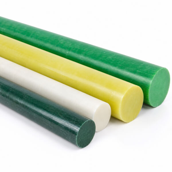
Pultruded rod has one characteristic weakness that belongs at the centre of any selection discussion: the pultruded rod has no hoop fiber to hold a transverse load together. All its reinforcement runs one way. Squeeze a clamp around it, drive a transverse pin through it, or apply an eccentric side force at an end, and the stress tries to open the rod along its fibers. The result is a through-split running the length of the part — and once the split reaches the end fitting, the fitting can slide off and the connection is lost.
This is not a theoretical concern. It is the reason end fittings on pultruded insulating linkages are often given a circumferential reinforcement band at the grip region, and the reason a wrapped rod is specified for any support that sees a hard radial clamp. It also explains a familiar field observation: a rod that carries a modest axial load without complaint fails after a side bracket is bolted to it. The bracket did not overload the rod in tension; it introduced the one load direction the fiber layout cannot defend.
Wrapped rod does not split this way because its concentric layers and cross-directional reinforcement close the crack path. That is the real premium you buy — not a higher dielectric number on a brochure, but resistance to the failure that actually removes parts from service.
Once shape and process are settled, grade selection is more straightforward. The families below are the ones encountered in switchgear rod stock; the temperature figures are continuous-duty guides, not short-term peaks.
| Grade | Resin system | Continuous duty | Why choose it | Watch-out |
| G-10 (EP GC 201 family) | Epoxy / E-glass | ~130–155°C (Class B–F) | General-purpose baseline; stable dielectric in humidity, good strength, economical | No flame rating; keep to enclosed or oil-filled duty |
| FR-4 | Flame-retardant epoxy / E-glass | ~130–155°C | UL 94 V-0 for dry-type and open compartments and code-driven panels | Flame retardancy does not extend the thermal ceiling |
| G-11 (EP GC 203) | High-temperature epoxy / E-glass | ~155–180°C (Class F–H) | Retains mechanical strength at temperature; the choice for hot compartments | Not inherently V-0 — pair with enclosure barriers or step to FR-5 |
| FR-5 | Flame-retardant high-temperature epoxy | ~155–180°C | High temperature and V-0 flame rating together | Premium cost; only where both demands apply |
| GPO-3 | Polyester-glass compound | ~130–155°C class | Excellent arc and track resistance; established in switchgear barriers | Mostly supplied as sheet or moldings — confirm rod availability before designing in |
Two cautions follow. First, flame rating and thermal class are separate axes: a drawing that asks for "G-10, V-0" has described FR-4, not G-10. Second, a high grade cannot rescue the wrong process: a G-11 pultruded rod still splits under a hard side clamp, because the resin change did not add circumferential fiber. Grade answers the environment; process answers the load direction. Keep the two questions apart.
This is where a rod is genuinely easier than a tube. A thread cut into solid stock is a real design freedom, not a machining compromise — the rod becomes its own threaded member, the mating part is a nut or a clevis, and there is no thin wall to crush under a clamped sleeve. Shoulders, flats, drilled cross-holes, and reduced-diameter spigots can all be turned into the same blank.
Three rules keep that freedom from becoming a failure:
Do not put a thread where a side load enters. On a pultruded rod a threaded, notched region is also a split-initiation site. Keep threads in low-radial-load zones, shorten the engagement, or add a reinforcement band at the grip.
Seal every machined face. Cutting across the fibers exposes fiber ends that wick moisture into the section. Wrapped rod in particular should have cut ends and drilled holes sealed after machining; an untreated machined surface turns a good dielectric into a moisture path.
Design out bearing on bare laminate. A transverse pin through a rod needs a metal insert or a locally reinforced boss so the bearing load lands on metal. The same local-reinforcement logic that protects a pultruded rod's end applies here.
Where the interface is adhesive rather than threaded, length of engagement beats adhesive strength: a long bond line spreads both service load and thermal-cycling strain. And because the metal fitting and the composite expand at different rates, a flexible adhesive system tolerates the differential better than a rigid one.
A rod has fewer insulation surfaces than a tube, which is a legitimate advantage — but the two it has still have to be designed:
Along the length (creepage). For an operating linkage or a standoff between live and earthed metal, the outside surface governs. Set the exposed length from creepage per kilovolt for the pollution class, and add sheds or a hydrophobic finish where the cubicle is compact or contaminated.
Across the section (dielectric). Where a rod passes through a barrier or spaces two phases, voltage crosses the section. Here the perpendicular dielectric strength and the absence of internal voids matter; specify a void-controlled wrapped product for high-voltage duty and verify with a partial-discharge figure rather than a breakdown claim alone.
Surface finish is therefore a dielectric property, not a cosmetic one. A machined rod with fiber pull-out or a rough transverse finish collects contamination and tracks early; a smooth, sealed surface holds its creepage strength far longer. Moisture uptake for electrical-grade epoxy-glass rod is low — typically around 0.5% or less over 24 hours — but what matters is where that moisture goes, and unsealed cut ends give it a direct route inward.
Knowing the boundary in both directions keeps the specification honest:
The part needs an internal bore. A vacuum interrupter's contact-pressure spring stack, a conductor passing through, or mass removed from a fast linkage all call for a tube. You cannot machine a functional bore into a rod and keep the economics.
Radial pressure must be carried by hoop fiber. A hard external clamp, internal pressure, or a burst-prone duty wants wound architecture, not a solid unidirectional section.
Moving mass dominates. A long linkage accelerated on every operation is stiffer per gram as a thin-wall tube. A solid rod of equal stiffness weighs more and slows the mechanism.
These are not criticisms of rod stock; they are reminders that the switchgear contains both shapes for good reasons. The companion discussion on pull tubes covers the other half of the decision. The point is to pick the shape first and argue about grades second.
A rod specification is only as good as the checks on the delivered part. Require the lot certification to state the resin system and grade designation — NEMA LI 1 grade, IEC 61212 rod class, or the applicable EP GC family — rather than accepting a generic "epoxy rod" label. Confirm the process: pultruded and wrapped rod are not interchangeable even at the same grade. Then check the finished part, not just the material: diameter tolerance and straightness, dielectric withstand, partial discharge for high-voltage duty, and — where side loads exist — evidence that the end design has been proven against splitting. A grade column on a data sheet answers none of those questions.
Not in the breaker pull path — that member is usually a hollow wound tube. Solid rods sit where the load is axial, compressive, or cantilevered and no bore is needed: busbar support insulators and standoffs, disconnector and load-break switch operating linkages, phase spacers, insulating tie rods and threaded shafts, and contact-rod guides. The choice of rod over tube follows the load and the end geometry, not habit.
Pultrusion lays continuous fibers straight down the length: high axial tensile strength, low cost, continuous lengths, but weak radial compression and no circumferential reinforcement, so a hard clamp or side load can split it lengthwise. Wrapped (laminated) rod builds up resin-impregnated cloth in concentric layers: lower pure tensile strength, but far better radial and impact strength, tighter tolerances, and lower partial discharge. Choose pultruded for light axial duty; choose wrapped for high voltage, side loads, and precision machining.
Because all the fibers run in one direction. A pultruded rod has no hoop fiber to hold a transverse load together, so a clamp squeezed around it, a transverse pin, or an eccentric side force drives a crack along the fiber direction — a through-split that can let the end fitting slide off. The countermeasure is a circumferential reinforcement band at each end, or simply specifying a wrapped rod where side loads exist.
Yes — and that is one of the real advantages of solid section over tube. Threads, slots, flats, and shoulders can be machined directly into a solid rod, so the fitting becomes a nut or a clevis rather than a sleeve clamped over a thin wall. On a pultruded rod, keep threaded regions short and away from high radial loads, or reinforce them; on a wrapped rod, seal machined faces because exposed fiber ends wick moisture.
G-10 (IEC EP GC 201 family) is the general epoxy-glass baseline to about 130–155°C. FR-4 adds UL 94 V-0 flame retardancy for open or dry-type compartments. G-11 (EP GC 203) holds mechanical strength at 155–180°C; FR-5 is its flame-rated partner. GPO-3 is a polyester-glass compound valued for arc and track resistance, but it is mostly supplied as sheet and molded parts, so confirm rod availability before designing it in.
Use a tube when the part needs an internal bore — the contact-pressure spring stack in a vacuum interrupter, a conductor passing through, or mass removal from a fast-moving linkage — or when radial pressure must be carried by hoop fiber. A rod is the wrong shape for those duties; a tube is the wrong shape when you need to machine a thread into the section or resist a hard transverse clamp without splitting.


