
Views: 0 Author: Fenhar Publish Time: 2026-09-24 Origin: Site


Ask a supplier for a composite tube and the first sentence back is usually a process name — filament wound, roll-wrapped, pultruded — as if the process were a quality grade. It is not. The winding method is a set of choices about where the fiber points and how tightly the resin consolidates, and those choices decide which axis of performance the tube is strong on and which it quietly gives up.
For a structural tube, the choice is a weight-and-cost story. For an electrical insulating tube it is a life-or-death story, because the axis most winding literature ignores — dielectric integrity — is the one the part is actually there to provide. This guide works the problem from the three axes that actually decide performance, then turns them into a selection rule you can apply from a drawing.
Three processes appear on almost every quote, and they are routinely presented as a ladder from best to cheapest. That framing is the first mistake. They are not ranks; they are different answers to two questions: which way do the fibers run? and how completely does the resin fill the space between them?
Filament winding lays continuous glass roving — resin-wet or supplied as prepreg — onto a precision mandrel at a controlled angle and under controlled tension. The fiber runs unbroken from one end of the tube to the other, so there is no seam and no joint. Rotation plus a traversing carriage lets the builder choose the winding angle fiber by fiber.
Tape or sheet winding (often called roll-wrapping) wraps glass fabric or paper tape in a spiraling, overlapping band around the mandrel, then cures it under pressure. It carries a bias seam where the wrap starts and ends, but it is flexible on wall thickness and geometry, cheap to run, and easy to machine.
Pultrusion is not a winding method at all. Fiber is pulled straight through a resin bath and a heated steel die, so every reinforcement runs at 0° — parallel to the tube axis. It is continuous, fast, and inexpensive, but it puts almost no fiber around the circumference.
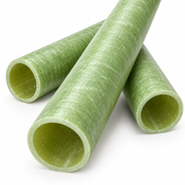
The single biggest lever a winding method gives you is the winding angle, because it sets where the strength lives. A layer wound near 90° (circumferential) resists bursting and crushing; a layer wound near 0° (axial) resists pulling and bending. Everything between is a compromise between those two.
The textbook case makes the trade explicit. In a closed-end pressure vessel the hoop stress is twice the axial stress, so the angle that makes the laminate exactly twice as strong circumferentially as axially works out to about 54.7° — the so-called magic angle. Drop to a low angle, say 15–30°, and the tube becomes a stiff axial member good for cantilevered supports and shafts but weak against internal pressure. Push toward 90° and it becomes a pressure vessel that has almost no axial grip. Hybrid layups stack several angles to get a bit of everything, at the cost of build complexity.
For electrical tubes the same physics rules the choice:
| Winding method | Fiber form | Dominant orientation | Best at | Watch out for |
| Filament winding | continuous roving, wet or prepreg | tunable 15°–90° | hoop / burst, thin wall, concentricity | cost, lead time, hard machining |
| Tape / sheet winding | glass fabric or paper, spirally overlapped | near-circumferential with bias | cost-effective, dielectric, machinable | lower compressive, delamination risk |
| Pultrusion (non-winding) | roving pulled 0° through a die | axial (0°) | axial / flexural, cheap, continuous | almost no hoop; splits under pressure |
The sentence worth memorizing: every winding angle is a decision to be strong in one direction by being weaker in another. There is no angle that is "best"; there is an angle that matches the load. A fuse cutout tube that must absorb an arc-pressure spike wants a balanced 45–55° or a near-circumferential layup. A busbar support that mostly carries axial thrust or a side load wants a low angle or a pultruded orientation. The angle is not decoration — it is the load path.
Here is where the generic filament-winding article stops and this one has to keep going. Most winding literature measures tensile, burst, and flexural numbers and calls the tube qualified. For an insulating tube that is only half the job, because the tube is itself the dielectric.
A void — an air pocket trapped between rovings, an area of incomplete impregnation, the discontinuity where a wrap starts and ends — is a partial-discharge site waiting for voltage. Air breaks down at a field strength far below the surrounding resin, so the pocket ionizes locally, the field there concentrates further, and discharge begins at a voltage well below what the solid material could have withstood. Left running, that discharge attacks the polymer chain, chars a conducting path, and grows a carbon track. The tube can look perfect on the outside and fail electrically from the inside.
This is why winding method, not just resin choice, decides dielectric life:
Wet winding uses winding tension to squeeze excess resin and trapped air out as the fiber lays down, which is why a well-run wet process gives good air-tightness and low void content.
Dry / prepreg winding controls resin content up front, so the cured laminate is uniform and the void fraction is predictable rather than accidental.
Semi-dry winding adds a drying stage between impregnation and lay-down to drive off low-molecular volatiles, which shrinks the voids that would otherwise form as the resin cures.
The interface is the weak point to watch. Damage does not usually start in the bulk glass-resin mix; it starts at a boundary — between two wound layers, or between the structural wall and any sheath or insert. Electric treeing initiates at precisely these interfaces, which is why a tube's track record depends as much on bond quality as on fiber angle. Partial-discharge testing (IEC 60270) is the honest way to measure whether the winding actually achieved a void-free, interface-clean part.
As a sanity check on scale, a well-made epoxy-glass insulating tube typically publishes a dielectric strength in the 20–30 kV/mm range and a volume resistivity above 10⊃1;⊃2; Ω·cm, with water absorption under 0.3% and a fiber volume around 60–70%. Those numbers are achievable precisely because the winding consolidated the laminate; the same resin in a poorly consolidated tube will not deliver them, and no datasheet line will warn you.
The third axis is geometric, and it matters for two reasons at once. A tube built on a precision mandrel — the filament-winding case — ends up with the tightest inner diameter and the most uniform wall around the full circumference. That uniformity is not cosmetic: in a dielectric, a thin spot is a low-breakdown-voltage spot, and in a precision assembly a wall that varies around the circumference is a part that seats crooked and concentrates stress at one edge. The rolled or seamed tube carries a bias seam and a small wall variation; the pultruded tube gets an excellent outer diameter from the die but only a moderate inner diameter.
For thin-wall precision tubes — fuse bodies, interrupter housings, medical and cryogenic insulation — concentricity is the actual constraint, and it is the reason filament winding exists as a category. A pultruded or rolled tube can be "good enough" on a thick, loose-tolerance wall, but the moment the wall gets thin and the fit gets tight, the seam and the wall variation become the whole problem. Dimensional stability under the thermal cycling of switchgear depends on the same uniform consolidation, because uneven cure means uneven expansion.
| Property | Filament wound | Tape / roll-wrapped | Pultruded |
| Seam | None | Yes (bias seam) | None |
| Wall uniformity around circumference | Uniform | Varies slightly | Good |
| Concentricity (ID control) | Best | Fair | Moderate |
| Hoop strength for a given wall | Highest | Lower | Lowest (axial bias) |
| Cost / lead time | Highest / longest | Lower / shorter | Lowest / shortest |
Put the three axes together and the selection rule is straightforward: decide which failure ends the tube's life, then pick the orientation and consolidation that defend against that failure. The matrix below turns the theory into a drawing-review checklist.
| Application | Dominant failure mode | Winding choice | Why |
| Fuse cutout / interrupter tube | internal pressure spike, burst | filament wound, balanced 45–55° or near-circumferential | burst resistance and no seam; the tube must contain an arc event without splitting |
| Busbar support / spacer | axial thrust, bending, dimensional creep | filament wound low-angle or pultruded | axial rigidity and roundness; load is push, pull, or side-load, not pressure |
| Transformer bushing sleeve | dielectric breakdown, tracking, creepage | filament or tape wound, void-controlled | void-free laminate = partial-discharge-free; concentric wall protects creepage distance |
| Coil former / capacitor sleeve | thin-wall fit, tight ID | filament wound thin-wall | concentricity and no seam at small wall; seats true in a winding or termination |
Two notes keep the matrix honest. First, the orientation that defends against the mechanical failure is necessary but not sufficient for an insulator — it must be paired with void control, or the dielectric axis fails anyway. Second, "tape wound" is not a downgrade for dielectric duty; a well-cured tape-wound sleeve is cheap, machinable, and electrically sound, which is exactly why it is common in bushing and cable-guide roles. The method earns its place by matching the failure mode, not by appearing at the top of a ranking.
The winding decides orientation and consolidation; the resin decides what the tube survives chemically and thermally. Epoxy dominates electrical grades because of its adhesion and low void tendency. Cycloaliphatic epoxy adds tracking and UV resistance for outdoor exposure; silicone-modified epoxy tolerates thermal cycling; the more exotic polyimide or cyanate-ester systems are reserved for extreme-temperature duty. Post-curing raises the glass-transition temperature and stabilizes the dielectric properties over the service life.
Thermal class follows the resin-and-glass system, not the winding: a standard epoxy-glass tube sits at Class F (155°C) and Class H (180°C). Moisture is the quiet enemy of the dielectric axis — low water absorption (under 0.3% for a well-made tube) keeps surface leakage and partial discharge at bay in humid service, which is another reason consolidation quality, not just the resin label, drives real-world performance.
Pultrusion remains the right answer when the load is axial or flexural, the cross-section is constant, and cost per meter leads. It is the wrong answer when the tube must contain pressure or hold a tight inner diameter, which is why a pultruded fuse tube is a known field failure and a pultruded bushing sleeve cannot match a wound one on concentricity. Centrifugal casting and braiding fill narrower niches. The decision is not "wind or not" — it is "which fiber path and which consolidation defend the failure mode in front of you."
No. Filament winding is strongest where the load is circumferential — hoop, burst, and crush resistance, plus the best concentricity of any round-tube process. But on a pure axial pull or a bending span it loses to pultrusion, whose fibers run straight down the length. "Strongest" is axis-dependent: the right process is the one that matches the failure mode, not the one with the best brochure.
Match the angle to the dominant load. A tube that must contain an internal pressure spike — a fuse cutout or interrupter housing — wants a balanced 45–55° helical or a near-circumferential layup for burst resistance. A busbar support or standoff that mostly carries axial thrust or a side load wants a low-angle or pultruded orientation for stiffness. Then, because the part is a dielectric, pair the orientation choice with void control: a well-consolidated tube outlasts a poorly cured one regardless of angle.
Yes — not by changing the resin, but by changing consolidation. The same epoxy and glass can land at very different partial-discharge inception voltages depending on how many voids the winding traps and how uniform the wall ends up. A filament-wound tube with entrained air pockets can be a worse insulator than a carefully cured tape-wound tube. Dielectric strength is an outcome of how the tube was made, not just what it was made from.
Because for an insulating tube the material is the dielectric itself. A micro-void that is harmless inside a structural shaft becomes a partial-discharge site inside an insulator: the air pocket ionizes, the local field concentrates, and over time the discharge attacks the polymer chain and grows a conducting carbon track. The failure is electrical, silent, and progressive — the tube can look intact right up until it flashes over. In a structural part that same void mostly just lowers a strength number you were not using.
Winding method is not a quality grade you read off a quote. It is three coupled decisions — fiber orientation (the hoop-versus-axial barter), void content (the dielectric axis that decides whether the insulation tube fails electrically), and wall uniformity (the concentricity that decides whether it seats true and breaks down evenly). Specify the insulation tube by its failure mode: pick the orientation that defends the mechanical load, then insist on the consolidation that defends the dielectric one, and verify the second with a partial-discharge number rather than a promise.


